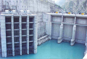
Intake Design for Hydro Power Plants

a. Type of intakes
Intakes may be classified as low pressure, or high pressure, according to the head on the inlet, but there is no definite line of demarcation separating the two types. For low-head plants and for developments where the pool drawdown is small, low-pressure intakes are used. If the pool drawdown is to be large, such as on many multipurpose projects, the intake will be of the high-pressure type.
It is advantageous to locate the intake high as practicable in order to minimize weights and travel distance of gates, size of hoist, etc., as well to keep the sill above possible silt deposits. Low pressure intakes are usually incorporated in the dam and, for low-head plants, are also part of the powerhouse structure. High-pressure intakes may be in the dam itself or may be in a separate structure or structures in the forebay. The essential requirement if the two types are the same, but the details and equipment may be radically different. Features common to practically all intakes are: trash racks, gates, steel bulkheads, concrete stoplogs, or all three, and converging water passage or passages.
b. Shape of intake.
The lines of the intake should be carefully laid out to obtain water velocities increasing gradually from the racks to the penstock, or to the spiral entrance. Abrupt changes in area of the water passage should be avoided in order to minimize turbulence and consequent power loss. The sections between the rectangular gate and the round penstock entrance is particularly important. The transition is ordinarily made in a distance about equal to the diameter of the penstock. Model tests are of great value in determining a satisfactory shape of intake, especially if Juvenile Fish Bypass is a design consideration.
c. Trash racks.
Trash racks are usually vertical in order to economize on length if intake structure. For low-head intakes, however, where the increase in length of structure would be small or where considerable trash accumulation may be expected, they are often sloped to facilitate raking. Water velocities at the racks should be kept as low as economically practicable with a maximum, for low-pressure intakes, of about 4 feet per second. For high-pressure intakes, greater velocities are permissible but should not exceed about 10 feet per second.
d. Gates
Provisions for emergency closure of the intake downstream from the racks is necessary to protect the generator unit. A vertical lift gate in each water passage is usually provided and is normally suspended just above the roof of the intake from a fixed hoist. On very low-head multiunit plants a single set of intake gates operated by a gantry crane is adequate and will be less expensive than individual gates operated by fixed hoists.
In either type of installation, self-closing tractor gates capable of operating under full flow are provided. Fixed wheel gates may be the most economical type for intakes where a gantry crane will be used for operation. Bronzebrushed wheel bearings should be used if the wheels will be submerged when the gate is in the stored position,otherwise, antifriction bearings can be used. For all but the lowest head intakes, “caterpillar” type gates with corrosion-resisting steel rollers and tracks have been found to be the most economical.

